 Print / download the product sheet
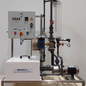
The MINIREG / L bench is designed for study and experimentation on a level control loop.
The bench includes the control loop, measurement instrumentation, indication, recording and control.
Disturbance circuits, step or other models make it possible to highlight the response of the process.
The bench covers a large number of themes that can be developed :
- Level measurement,
- Adjustment and calibration of the level sensor,
- Initiation to control and regulation,
- Automatic regulation methods,
- Setting by discontinuous actions,
- Regulator P,
- PI regulator,
- PID controller.
- Regulatory strategies,
- Process response,
- Time analysis,
- Precision and stability of a loop,
- Control valves,
- valve positioner,
- Electric transmitters,
- Intensity-pressure converter,
- Digital systems.
Operative part
The bench consists of a chassis incorporating :
- A main tank.
- A plexiglass tank graduated in liters and in cm of water column comprising:
- A level sensor: relative pressure transmitter 0/50 m bar, 4/20 mA output,
- A centrifugal pump,
- A pneumatic control valve,
- A P / I converter,
- A set of manually operated valves,
- A disruptive level circuit.
- Sound level 70 dB (A),
- Volume of the tank: 30litres,
- Sanitary water.
Control part
An electrical cabinet including :
- Equipment for supply and protection of the installation,
- The control organs,
- Shunts giving access to the 4/20 mA measurement of the sensors and the valve,
- RS 232C link for supervision,
- A digital controller, ASCON.
The front panel gives clear operator information.
Supervision
A set of supervision is included in the supply of the base bench. It is composed of :
-Software "SUPERVI SEUR MINIREG / L", developed on Autolink
-A connecting cable,
-A key to protect the software.
This set requires the use of a PC-compatible microcomputer, running on XP or Windows 7
Supervisor MINIREG / L
The MINIREG / L supervision software is structured on the basis of several screens, and allows to visualize :
- The general synoptic of the regulation with the digital display of the various regulation parameters,
- The front of the digital controller with the graph bar animation corresponding to PV, SP and OP,
- The numerical display of the values of PV, SP, OP, xp, ti and td,
- The command giving access to the modifications of the values of SP, xp, ti and td,
P V: process variable,
SP: Consigne,
OP: Command signal,
xp: proportional band,
ti: Integration time,
td: Derivation time.